Weekend Project: Nerf Dart Counter (Ammo Counter)
Recently I bought a Nerf Retaliator for my son on his birthday. I was scouting thingiverse for some accessories to print like Nerf Sight, then I came across AmmoCounter Mk1 Scope Case by Nathaniel Deal. Ammo counter lets you specify the magazine size and it will count down as you fire each shot. It will let you know how many bullets are left at any point of time. It is particularly useful for rapid fire guns and guns with 12, 18 or higher capacity magazines.
AmmoCounter Mk1 Scope Case has a nice scope face which can accommodate two 7-segment displays, 2 push button switches and an on-off switch. It has a separate compartment for 9V battery, has openings to route the sensor wire and has removable tracks to put it on the tact rail. Over all a very well designed case. I was really impressed with the counter and decided to build one for my son.
Dart Counter mounted on top of the Barrel extension
A small video with Dart counter in action
The case is not perfect for a Retaliator for 2 reasons:
1. The muzzle does not have an option to attach the Barrel Adapter
2. If I attach the case on the priming rail, it interferes with cocking of the gun.
I decided to put the case on top of Barrel extension and to somehow fix a sensor inside the Barrel extension. That way it will be a single unit which can be removed from the gun when necessary.
Read on to find out how I went about doing it.
Micro controller and Electronics:
My initial thought was to hook up an Arduino pro mini (because of the small size) with an I2C OLED display and to attach the IR sensor to the gun. But then I will have to redesign the Scope case to fit an LCD and even otherwise OLED seemed an overkill. I decided to use the case from Nathaniel Deal and build my hardware around it. The requirement was to connect two 7-segment displays 1 on-off switch and 2 momentary push button switch to the scope face. Attach an object sensor of some kind to the Barrel Extension to sense the bullets. Have a micro controller board to control all these.First round, hooked up a 7 segment display to an Arduino Pro Mini board with a 7447 BCD to 7-segment decoder.
Arduino driving a 7-segment display through 7447
Then I realized that the Pro mini has so many GPIOs that I can directly connect two 7-segment displays, 2 switches and a sensor and still be left with a few GPIOs. I had an IR based Obstacle sensor board which I used as the sensor (later this was changed) and the whole setup looked like below, with a whole-lotta wires.
two 7 segment displays, 2 switches and a sensor connected to Arduino
Fritzing sketch to make things clear. I know that it is a bad idea to drive all 14 LEDs with a single resistance, but the general purpose PCB I was using to mount the display did not have enough real estate for individual resistances and I was lazy to make another board.
Fritzing diagram of the setup
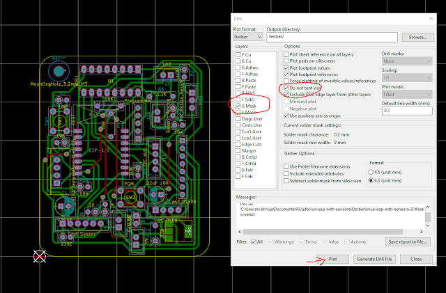
Schematic
The obstacle sensor was later replaced with a simple setup as below. Tested the setup and I was getting close to 5V when the IR was directly falling on the sensor and close to 0 when the IR was obstructed. Plenty enough variation for the GPIO to detect it as 1 and 0.
IR LED sensor pair
I used a a general purpose PCB cut to the size of the scope face. Soldered the 7-segment display and the switches onto it. Connected everything to break away headers soldered onto the back of the board and used ribbon cable jumper wires to connect it to Arduino Pro Mini. The ribbon cable is longer than ideal so the case is really crammed. But because of that nothing moves inside the box :-)
Software:
Now for the software part, I wrote a small program in Arduino IDE, the only library it uses is LowPower which makes it easy to put Arduino in power save mode to conserve battery.
At present the code does the following:
- One button cycles through all the predefined magazine sizes, now i have kept 6,10,12 and 18
- Next button resets the counter to now set magazine size.
- Every time a dart goes through the barrel, the count is decremented by 1.
- Once it hits zero and if another shot is fired, it assumes that a new magazine was inserted, and so it goes to set magazine size minus 1.
- It goes to power save mode if the gun is idle for 60 seconds. In power save, the display is turned off and the micro controller goes to deep sleep. Only a button press or another shot can bring it back online.
Code is available at https://github.com/vishnujs-diy/DartCounter
This file contains bidirectional Unicode text that may be interpreted or compiled differently than what appears below. To review, open the file in an editor that reveals hidden Unicode characters.
Learn more about bidirectional Unicode characters
/* | |
* DartCounter | |
* | |
* Created on: Nov 18, 2018 | |
* Author: vishnujs | |
* vijasu@gmail.com | |
*/ | |
#include "LowPower.h" | |
#define ON 1 | |
#define OFF 0 | |
#define DEBOUNCE_TIME 100 // 100ms | |
#define IDLE_TIMEOUT 60000 // 1 min | |
#define COUNTER_INPUT 2 | |
#define BTN_RESET 3 | |
#define BTN_SET_MAG A4 | |
// A B C D E F G A B C D E F G | |
volatile int SevenSegPins[2][7]={{10,11,12,13,A0,9,8},{6,7,A1,A2,A3,5,4}}; | |
volatile int counter; | |
volatile unsigned long last_interrupt; | |
volatile int display_state; | |
volatile int mag_size; | |
/* | |
* Since the Seven segment display is wired directly, use the following table for displaying numbers | |
* +-A-+ | |
* F B | |
* +-G-+ | |
* E C | |
* +-D-+ | |
*/ | |
int digits[10][7] = {//A,B,C,D,E,F,G | |
{0,0,0,0,0,0,1}, // 0 | |
{1,0,0,1,1,1,1}, // 1 | |
{0,0,1,0,0,1,0}, // 2 | |
{0,0,0,0,1,1,0}, // 3 | |
{1,0,0,1,1,0,0}, // 4 | |
{0,1,0,0,1,0,0}, // 5 | |
{0,1,0,0,0,0,0}, // 6 | |
{0,0,0,1,1,1,1}, // 7 | |
{0,0,0,0,0,0,0}, // 8 | |
{0,0,0,0,1,0,0} // 9 | |
}; | |
/* | |
* Predifine MAG sizes here. | |
*/ | |
#define MAX_MAG_SIZES 4 | |
int mag_sizes[MAX_MAG_SIZES] = {6,10,12,18}; | |
/* | |
* Set a digit onto a seven segment display | |
*/ | |
void setDigit(int pinArray[7], int digit) { | |
if (digit > 9) { | |
return; | |
} | |
for(int i=0;i<7;i++) { | |
digitalWrite(pinArray[i],digits[digit][i]); | |
} | |
} | |
/* | |
* Set a number to the display | |
*/ | |
void setNumber(int num) { | |
setDigit(SevenSegPins[0],num%10); | |
setDigit(SevenSegPins[1],num/10); | |
display_state = ON; | |
} | |
/* | |
* reset display to mag size | |
*/ | |
void resetCounter() { | |
counter = mag_sizes[mag_size]; | |
setNumber(counter); | |
} | |
/* | |
* Timer 1 call back, timer1 is set to 1sec interval. | |
* This is used to switch of the display and put the uC to deep sleep. | |
* This helps in bringing down the power consumption from ~30mA to ~18mA. | |
* Cannot bring it down further as the IR sensor, power LED and pin 13 LED will be on. | |
* Power LED 3mA, pin 13 3mA, IR sensor with opAmp 12mA, uC in sleep takes only 0.3mA | |
*/ | |
ISR(TIMER1_COMPA_vect){//timer1 interrupt 1Hz | |
/* | |
* Check if we have reached idle time. | |
*/ | |
if (((millis() - last_interrupt) > IDLE_TIMEOUT) && display_state != OFF) { | |
/* | |
* Switch off the display | |
*/ | |
for(int i=0;i<2;i++) { | |
for(int j=0;j<7;j++) { | |
digitalWrite(SevenSegPins[i][j],1); | |
} | |
} | |
display_state = OFF; | |
/* | |
* Set uC to deep sleep for ever | |
* It will wake up on interrupt. | |
*/ | |
LowPower.powerDown(SLEEP_FOREVER , ADC_OFF, BOD_OFF); | |
} | |
} | |
/* | |
* handle pin change interrupt for A4 which is the set mag pin | |
*/ | |
ISR (PCINT1_vect) { | |
unsigned long now = millis(); | |
/* | |
* SW Debounce | |
*/ | |
if (now - last_interrupt < DEBOUNCE_TIME) { | |
return; | |
} | |
/* | |
* Tickle last interrupt | |
*/ | |
last_interrupt = now; | |
/* | |
* Move Mag size to next and reset. | |
*/ | |
mag_size = (mag_size+1)% MAX_MAG_SIZES; | |
resetCounter(); | |
} | |
ISR (PCINT2_vect) { // handle pin change interrupt for D2 which is the reset pin | |
/* | |
* Tickle last interrupt | |
*/ | |
last_interrupt = millis(); | |
/* | |
* Reset | |
*/ | |
resetCounter(); | |
} | |
void counterInterrupt() { | |
/* | |
* Tickle last interrupt | |
*/ | |
last_interrupt = millis(); | |
/* | |
* reduce counter, | |
* If the counter is at 0 and we get an interrupt, that means the mag has been reloaded and a shot was fired. | |
* if so, reset the counter and reduce 1 | |
*/ | |
if (counter) { | |
counter--; | |
} else { | |
counter = mag_sizes[mag_size] - 1; | |
} | |
setNumber(counter); | |
} | |
/* | |
* Enable pin change interrupt | |
*/ | |
void pciSetup(byte pin) | |
{ | |
*digitalPinToPCMSK(pin) |= bit (digitalPinToPCMSKbit(pin)); // enable pin | |
PCIFR |= bit (digitalPinToPCICRbit(pin)); // clear any outstanding interrupt | |
PCICR |= bit (digitalPinToPCICRbit(pin)); // enable interrupt for the group | |
} | |
void setup() { | |
/* | |
* set all seven segment display pins to output | |
*/ | |
for (int i=0;i<2;i++) { | |
for(int j=0;j<7;j++){ | |
pinMode(SevenSegPins[i][j],OUTPUT); | |
} | |
} | |
/* | |
* set counter input and button pins | |
*/ | |
pinMode(COUNTER_INPUT, INPUT); | |
attachInterrupt(digitalPinToInterrupt(COUNTER_INPUT), counterInterrupt, FALLING); | |
pinMode(BTN_RESET, INPUT_PULLUP); | |
pciSetup(BTN_RESET); | |
pinMode(BTN_SET_MAG, INPUT_PULLUP); | |
pciSetup(BTN_SET_MAG); | |
/* | |
* Set mag size to default | |
*/ | |
mag_size = 0; | |
resetCounter(); | |
//set timer1 interrupt at 1Hz | |
TCCR1A = 0;// set entire TCCR1A register to 0 | |
TCCR1B = 0;// same for TCCR1B | |
TCNT1 = 0;//initialize counter value to 0 | |
// set compare match register for 1hz increments | |
OCR1A = 15624;// = (16*10^6) / (1*1024) - 1 (must be <65536) | |
// turn on CTC mode | |
TCCR1B |= (1 << WGM12); | |
// Set CS10 and CS12 bits for 1024 prescaler | |
TCCR1B |= (1 << CS12) | (1 << CS10); | |
// enable timer compare interrupt | |
TIMSK1 |= (1 << OCIE1A); | |
sei();//allow interrupts | |
} | |
void loop() { | |
} |
3D Printed parts and assembly
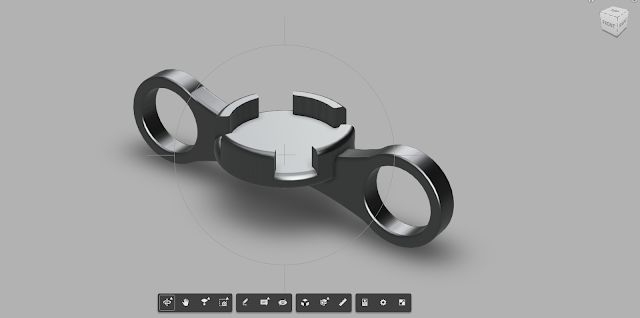
Designed a small sleeve again based on a design I saw from Nathaniel Deal.
I have posted it in thingiverse @ Ammo counter sensor Sleeve for Nerf Retaliator
This sleeve will go inside the Barrel Extension without having to cut or file anything inside the Barrel extension.You will need to drill 2 small holes on the tube inside the barrel to let IR pass through
Dart sensor
Dart sensor once fixed inside the barrel extension
Mounted on the barrel extension
He is happy, I am happy, weekend well spent!
Nice
ReplyDeleteAwesome work!!
ReplyDeleteI am trying this.
BreadBoard.PNG Connect as shown in the picture
But it doesn't work because the compilation is wrong.
What files do you need for the Arduino library?